MIDAS M32 vs DL153 Stagebox

Preamp/converter comparison

So again, in addition to the previous article regarding the Behringer X32 and the Midas M32, we wanted to clarify the question how the Midas M32 differs from the Midas DL153 in preamp / converter quality soundwise. On their website Midas claims, that the DL153’s preamps are Midas’ latest development and thus differs from those in the M32. Therefore we recorded some basic tracks with saxophone, guitar, speech, cymbals and snare.


12966029_1267759716585041_656167787_n


Signal chain:

Microphone (AKG C414/Beyerdynamic M400) —> Y-Split Cable

  • –> Midas DL153 -> via AES50 into M32 -> ProTools
  • –> Midas M32 –> ProTools

In order to avoid unwanted coloration due to splitter boxes using transformers in their isolated outputs, this time we decided to use a Y-Cable with all pins wired to both outputs.


Filedescription:

Fileformat is 48kHz, 24 bit, which it was also recorded in. Each take is split into 2 files, the DL153 and the M32 recording, which are sample-aligned. As all Midas preamps show a certain amount of saturation when driven hard, most of the takes had been repeated with different gain settings. All tracks were normalized to -1 dBfs. The file decription itself contains the application, the microphone model, Gain setting and the respective preamp/converter. (The maximum provided amount of analog gain is 45.5 dB on the M32 & the DL153, everything above means digital amplification of the signal !)

Downloadlink: Midas M32 vs DL153 Audiofiles


12957402_1267759629918383_116282140_n


Behringer X32 vs MIDAS M32

Preamp/converter comparison – Delay compensation

In addition to the previous article regarding the Midas M32 and the A-Designs Pacifica / Steinberg MR816 CSX, we were really interested in the question how the Behringer X32 would differ from the Midas M32 in preamp / converter quality soundwise. Therefore we recorded some basic tracks with guitar / speech. Furthermore we also used the Steinberg MR816 in comparison to the M32/X32 in order to find out, how they both would compare to a common “studio” signal-chain.

10478529_1043805978980417_1357995849798084868_n

As Midas claims their M32 to have fully latency-compensated buses (in advantage to the X32), we conducted a little experiment by inserting different fx in the M32’s buses, while recording the respective outputs (ChannelOut, Bus1 Out, Bus2 Out, Sum Out). Those tracks have been recorded in ProTools to visualize the delay between the different outputs. We tried the same thing on the X32 but we did not take any screenshots. As the downloadable description is written in german, here’s a short explanation:

  • Channel Out: Direct out from the channel (post – AD, pre – signal-processing)
  • Bus 9:   Channel routed to bus, Bus not routed to LR, no FX applied
  • Bus 10: Channel routed to bus, Bus not routed to LR, FX from slot FX1
  • Bus 11: Channel routed to bus, Bus not routed to LR, FX from slot FX5
  • Sum: Channel routed to LR, no processing

The result: The Behringer X32 will NOT compensate for latency introduced by inserted FX from the FX-rack. The bus channel’s EQ & COMP will not add any latency. The M32 though will compensate for latency, but only if the FX is inserted in Slot 1-4 in the FX-rack. This seems weird, as Slot 1-4 is intended for send-FX use. Maybe that’s also a firmware issue and will be changed with some new firmware, so far it works like that nevertheless.

2015-04-14 17.11.332015-04-14 17.11.55

Signal chain:

Microphone (AKG C214/Beyerdynamic M400/Shure Sm58) —> ART ProSplit into

  • –> Behringer X32 Rack –> Steinberg MR816 CSX (Adat In) –> Cubase
  • –> Midas M32 –> ProTools

 Filedescription:

Fileformat is 48kHz, 24 bit, which it was also recorded in. Each take is split into 2 files, the X32 and the M32 recording, which are sample-aligned. All tracks were normalized to -1 dBfs. Each take has then been repeated (e.g. Take1 & Take2), while switching the micsplitter’s outputs to quantify the influence of the micsplitter’s built-in transformer (= isolated out). The file decription itself contains the respective preamp, the application, the microphone model, the take number and the mic splitter’s output. (The applied gain settings are listed below – the maximum provided amount of analog gain is 45.5 dB on the M32 !)

X32 vs M32:

  • Take 1 & 2: Guitar, AKG C214, +35 dB Gain
  • Take 3 & 4: Guitar, Beyerdynamic M400, +45.5 dB Gain
  • Take 5 & 6: Speech, AKG C214, +38.5 dB Gain
  • Take 7 & 8: Speech, Shure Sm58, +45.5 dB Gain

X32 / M32 vs Steinberg MR816CSX:

  • Take 1 & 2: Guitar, AKG C214, +45.5 dB Gain X32
  • Take 3 & 4: Guitar, AKG C214, +45.5 dB Gain M32

Downloadlink: Behringer X32 vs MIDAS M32 Audiofiles

Midas M32 Preamp Shootout

Midas / the Music Group recently released the Midas M32 digital mixing desk, claiming that they massively improved the desk’s preamps and AD/DA converters compared to the Behringer X32. As it is also intended for studio applications a colleague and me decided to do a little shootout in order to find out how big the sonic difference would be compared to a common studio signal chain. Therefore we used an A-Designs Pacifica “Hi-End” preamp plugged into a Steinberg MR816 CSX, which is claimed to be on an RME-level soundwise/specwise. This is absolutely not a scientific experiment, it’s only about the subjective perception of the preamps’ and converters’ sound.

2015-02-04 13.52.35

Signal chain:

Microphone (AKG C214/LineAudio CM3/Shure Sm58) —> Micsplitter into

  • –> A-Designs Pacifica –> Steinberg MR816 CSX –> Cubase
  • –> Midas M32 –> ProTools

 Filedescription:

Fileformat is 48kHz, 24 bit, which it was also recorded in. Each take is split into 2 files, the Pacifica/MR816 and the M32 recording, which are sample-aligned. All tracks were normalized to -1 dBfs. The file decription itself contains the take number, the respective signal chain, the microphone model and the applied gain setting. As Midas claims their preamps’ popularity to derive from their color/saturation, when you drive them hard, take 2&3, 4&5, 6&7 only differ from each other in the applied gain setting on the M32. We btw realized that the M32 only provides 45.5 dB of analog gain, the left 14.5 dB is done internally (digital trim). The DAW will not recieve a hotter signal, if you use the trim, nor does it make any difference in sound.

  • Take 1: basic comparison between M32 and Pacifica/MR816 CSX –> AKG C214 @ acoustic guitar
  • Take 2 & 3:  applied gain differs –> LineAudio CM3 @ acoustic guitar
  • Take 4 & 5:  applied gain differs –> AKG C214 @ acoustic guitar
  • Take 6 & 7:  applied gain differs –> Shure Sm58 @ Vox

Downloadlink: Midas M32 preamp/converter shootout

2015-02-04 13.52.28 2015-02-04 13.57.34

DIY passive Monitor-Station

Building a passive volume control / input-output switch

Image

What’s the convenience of having an analog volume control over the built-in volume control in most interfaces? Most important is the fact, that by turning down the volume with the built-in volume control, the bit depth will drastically decrease, as most interfaces will reduce volume in the digital domain. (Except some high end gear like the UA Apollo!) So why spending hundreds of dollars on high end gear, when one won’t be able to hear, what’s really going on, even if your signal chain only contains the best gear (Monitors, converters, etc.). As a rule of thumb, 6db equals 1 Bit Resolution, meaning that reducing the output of your interface by e.g. 24 db will result in a resolution of only 20 Bits. On the other hand it’s quite handy having a monitoring station, where it’s possible to switch between different monitor pairs or different input sources.

The reason for me building a passive volume control myself, though there are alternatives galore on the market, was simply because I wanted to build something that would a) last for long and b) consist of high quality parts. There’s obviously nothing wrong with the current products one could buy, but for a price of 50 Euros average, one should not expect extraordinary quality. The DIY volume control is also about 50 Euro, but contains much better parts.

Now the question arises, why passive? Well, one the one hand it’s absolutely linear up to 50kHz (as long as cable length does not exceed 10 meters → HiCut / RC-circuit), on the other hand it’s just simple to build and straightforward. It’s only necessary to have a little soldering experience.

The most important part in this circuitry is the pot, this is why I chose to use an ALPS pot, that definitely provides a better gang-error (Gleichlauf) compared to the pots used in the common cheap volume controls. This is btw the reason to most high-end manufacturers for choosing an active circuitry due to the ability of providing equal volume on both channels (L&R).

There is only one problem, that still has to be considered: If I wanted to build a balanced volume control, I would need a four-gang pot, which is pretty big and expensive, because every signal theoretically needs it’s own “layer” on the pot. (2 Signals Hot/Cold for each L&R.) Therefore I found a solution on the web:

I used the pot in parallel as shunt, with the so-called shunt mod, so a dual-gang pot was just fine. The only drawback is that you have to connect all grounds together, so the whole gear should use the same power outlet, as well as all the cables’ shields should be connected.

The necessary switches should be four-pole three-position rotary switch (4×3), the middle position will form the “mute position” with nothing connected to it’s poles.

(It’s btw also possible to connect all of the poles on the output, thus being able to connect 3 monitor pairs!!!)

In the BOM you will also find 4 x 4K7 Ohm resistors, which will attenuate the signal by approximately 6dB, so the control range on our controller will be more “precise”.

BOM (Bill of materials) / What we need:

(I ordered those at BanzaiMusic Berlin)

Image

Attention: The enclosure I used turned out to be too small for all the parts, so I ended up with a 2 In 4 Out switch/control, so a bigger enclosure is necessary for a 4 In 4/6 Out switch!!!

and

ALPS dual-gang 10K logarithmic pot

ImageImage


HOW TO:

The entire procedure might not be complicated regarding the circuitry, but it’s quite an effort soldering all the necessary connections, therefore I will show step-by-step how to create your own DIY volume control.

1. Unpacking / Preparing

There are a few things to consider before we start soldering. After drilling the holes for the pot and the 2 switches in the enclosure, we need to clip off the switches’ “noses” to the needed length. This might sound quite trivial, but for beginners this definitely will be a problem. In the first place I also asked myself, how I can make all the parts fit my enclosure. There’s also a “nose/pin” on the pot, which should be removed by clipping off. (It’s also possible to drill a hole for the pin, but that’s much more complicated imho!)

2. Connecting the pot

At first I would recommend soldering all connections to the pot. Therefore the pot will not be connected in a normal way, but as “shunt” pot. Thus the pin layout on the pot is the following for each “layer” (L = Layer/Gang1; R = Layer/Gang 2):

1 In & Out Hot (Signal → R = 4K7Ω → Pot → Signal)

2 & 3 Connected together – In & Out Cold (Signal → R = 4K7Ω → Pot → Signal)

(Original pin layout would be: 1 Ground; 2 Out; 3 In)

For help check out the following pictures!!!

Image

ShuntMod2.gif

Regarding the upper picture: We will not connect pin 2&3 to ground, but instead this will be the cold signal !!!

3. Connecting the rotary switches

In the middle of each switch there are 4 pins for the respective signals:

A Left In / Out Hot

B Left In / Out Cold

C Right In / Out Hot

D Right In / Out Cold

Image

2014-03-15 02.17.27

The other pins, which are organized as circle will determine which signal will go to the pins in the middle and vice versa. Each pin in the middle will belong to 3 pins in the circle. In the next step the cables coming from the pot have to be soldered to the middle pins of the input switch, as well as to the ones on the output switch. Finally the “circle” pins have to be soldered to the contacts on the input / output stereo jacks. This example will make clear which cables the solder lugs have to be soldered to:

For the input switch:

Pin 1 = Signal 1 Left In Hot     →
Pin 2 = None                                       → Pin A = Left Out Hot
Pin 3 = Signal 2 Left In Hot    →

Pin 4 = Signal 1 Left In Cold    →
Pin 5 = None                                          → Pin B = Left Out Cold
Pin 6 = Signal 2 Left In Cold    →

Pin 7-9 contains Signal 1 / 2 Right In Hot, Pin 10-12 Right In Cold


For the output switch:
                                                   → Pin 1 = Out 1 Left Hot (Speaker pair 1)
Pin A = Left Out Hot   → Pin 2 = None
                                                   → Pin 3 = Out 2 Left Hot (Speaker pair 2)

                                                     → Pin 4 = Out 1 Left Cold (Speaker pair 1)
Pin B = Left Out Cold   → Pin 5 = None
                                                      → Pin 6 = Out 2 Left Cold (Speaker pair 2)
etc…


Now there’s still one thing missing. All the stereo jacks’ grounds have to be connected together from the input side to the output side!

After all the soldering insanity and assembling all the parts this thing should somehow look like this (as I already mentioned I left out the 2nd input due to missing space):

Image

Image

The switches now have the follwing function:

                                     → Position A: Input A
Input switch     → Position B: MUTE
                                     → Position C: Input B

                                      → Position A: Speaker pair 1
Output switch   → Position B: None / MUTE or additional speaker pair
                                      → Position C: Speaker pair 2

The volume control / switch just works fine and really solved a lot of problems for me. I absolutely recommend reading the instructions posted in the following files / links, which were quite a big help to me:

Click to access AT78_OTB.pdf

http://www.world-designs.co.uk/forum/showthread.php?t=5795

lorlin_rotaryswitch

If there is something I got wrong regarding electronics, please feel free to comment or improve something regarding the circuitry!!! Feel free to ask, if there’s something that did not become clear!

T-Bone RB500 / Nady RSM-2 / Apex 205 MOD

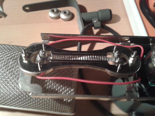
This time we´re gonna do some microphone modification. The main steps are removing the acoustic reflector shields around the T-Bone RB-500‘s ribbon motor, the mic housing’s inner screens and dampening the whole construction in order to avoid resonances. Furthermore we will retension the ribbon itself.

It’s up to you to decide, wether its worth the modification or not, as the mic’s frequency response is gonna change fairly much. It’s gonna loose some high-end, whereas it’s also gonna sound much more natural after the MOD.

Another point to be considered is that by removing the mic’s inner screens the microphone will become much more sensitive to wind blasts and high sound pressure level. Thus it’s not such a good idea to use it for REALLY loud sources (e.g. Kickdrums), but instead it will work well for rather acoustic sources (e.g. acoustic-guitar, overheads).

Nevertheless micing guitarcabs will still work properly in my experience. 

Attention: By modifying the microphone one will lose any warranty. I’m not responsible for any damage to the mic, nor for losing warranty.

Step 1: Removing the mic housing

2013-12-05 17.59.43 2013-12-05 18.00.33 2013-12-05 18.06.42 2013-12-05 18.00.44

– Remove the outer screws holding the mic’s housing

– Unscrew all the screws, which are holding together the mic’s housing (small & big screws)

– Carefully pull the lower housing from the micbasket

Step 2: Removing the mic’s acoustic screens

2013-12-05 18.09.29 2013-12-05 18.15.43

2013-12-05 18.16.31

– CAREFULLY unscrew all screws holding the mic’s reflector shields and remove them

– As visible on the picture my mic’s ribbon obviously was severely stretched, therefore we will come to retensioning the ribbon later

Step 3: Removing the micbasket’s inner mesh

2013-12-05 19.14.45

– Remove the micbasket’s inner screen/mesh using pliers

Step 4: Dampen the ribbon motor

–> This is not absolutely necessary, but will make the microphone less sensitive to mechanical vibration and reduce resonances

– Try to fill all the spaces between the ribbon motor and the assembly around it with loose foam, furthermore dampen the microphone’s lower part of the housing (“canister”) with foam

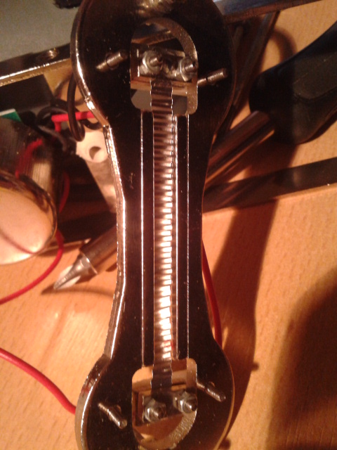
Step 5: Retensioning the ribbon

In this step I’m gonna give a short instruction how to retension the ribbon. As I’m relatively new to this kind of modification, you should read through other threads/blogs as well, to gather some information about the process. This is a very sensitive step, as the ribbon can easily be damaged !!!!
2013-12-05 18.23.41

–> This is how an obviously stretched ribbon looks like 😀

– Carefully unscrew all the screws, which are holding together the ribbon clamps and slightly try to lift the upper clamp

– I used a cotton swap/bud with some glue attached to its endings, to grab the ribbon and retension it

And here comes the most difficult part: Finding the right resonance frequency for the microphone, here is a short instruction I found on the web:

– Open any sequenzer (e.g. cubase, pro tools, …) and open an FFT-analyzer

– Connect the mic to an audiointerface and select the respective input

– Slightly and frequently tip on the magnets surrounding the ribbon

– The analyzer should now show a peak in the lower bass area

Bild 1

– The optimal resonance frequency for that specific ribbon construction should be approximately 30 Hz 

–> If the ribbon is too tight, a low-lowmid frequency bump will become noticeable! This should become quite obvious!

– As soon as you`re there close the clamps and attach the screws

2013-12-05 19.14.28 2013-12-05 19.24.34

– Reassemble the mic’s saddle and housing, now it should look like that:

2013-12-05 19.32.28 2013-12-05 19.32.40

So finally, how does it sound? Here’s some audio files, which clearly show the difference between the modified and the unmodified version:

Here is how the mic sounds, when the ribbon tension is too high (/or how it generally should not sound like):

There is btw also the possibility to swap the microphone’s transformer, which should alter the sound quite a bit in a positive manner. This can easily be achieved and really takes the mic to another level. Here’s a link with every piece of information one might need:

http://recordinghacks.com/2009/12/31/diy-ribbon-transformer-upgrade/

To dig in deeper, here’s some links I found really helpful: 

http://www.hometracked.com/2007/08/17/ribbon-mic-mod-part-1-apex-205/

http://moonroomrecording.blogspot.sk/2010/06/shinybox-ribbon-mic-mod.html

http://www.gearslutz.com/board/low-end-theory/356054-ribbon-retensioning.html

http://www.gearslutz.com/board/low-end-theory/433545-apex-205-ribbon-mic-transformer-mods.html

http://www.gearslutz.com/board/3803591-post6.html

http://www.gearslutz.com/board/so-much-gear-so-little-time/364989-chinese-ribbon-mic-buyers-guide-mr-joly.html

Mixbus Compression: Hardware vs Software

As MixBusCompression stays a highly discussed topic, I decided to do a quick shootout between the most common VCA Compressors I own and do frequently use for this specific type of application.

The contestants are:

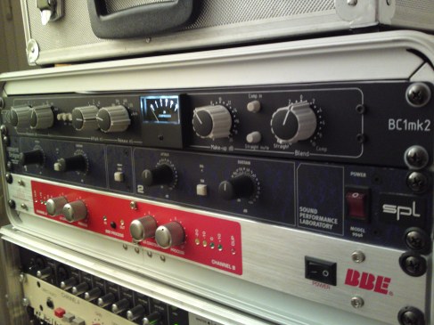
  •  TK Audio BC1 MkII

–> A pretty clean hardware SSL-Style Compressor

Image

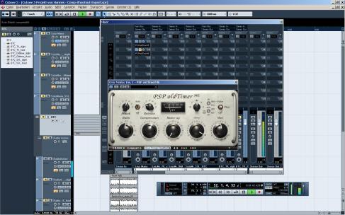
  •  PSP Audioware Oldtimer

–> Very flexible VCA-modeled software compressor with tube emulation

Image

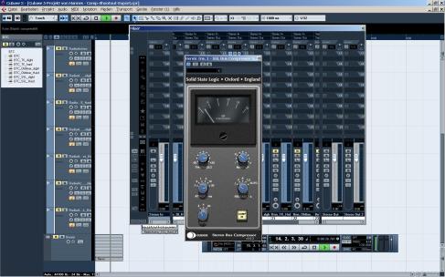
  •  SSL Duende Buscompressor

–> Software model of the famous SSL4000G-Series Buscomp

Image

Therefore the shootout contains 4 tracks from different kinds of music:

Szüz Maria (Hungarian Acoustic/Traditional – song)

Break the Cage (HeavyRock/Metal)

RadioActiveCrew (Techno/Minimal/Electronic)

Raumpilot (Minimal/Techhouse)

Notice: As I had to choose tracks without copyright, it’s not about the quality of the production itself!

For each individual track I applied 2 settings for comparison purposes. One slightly compressed version for a tad “Glue/Gel” or whatever you wanna call it and one with hard compression, where I tried to really smash things up.

Compressor settings are always hard to match, as every comp has its own set of knobs and possibilities, but for the slight buscompression examples I tried to apply the same settings I chose on the TK Audio and match as close as I could. The hard-compression settings differed alot and it’s only purpose is to show, how the different compressors react, when things really get smashed.

Regarding AD/DA Conversion, the signal flow stayed all the same for each file, including the original mix:

Cubase->Steinberg MR816Csx DA-> (TK Audio BC1 MKII->) Steinberg MR816Csx AD

Resolution: 44.100 Hz, 24 Bit,

(only available in 320kb .mp3 – .wav upon request)

The different settings for slight buscompression are:

– Szüz Maria:

  Ratio: 2:1 – HPF in – Attack:10mS – Release:Auto – GR: c.a. 2-3dB

– Break the Cage:

  Ratio: 1.5:1 – HPF in – Attack:10mS – Release:Auto – GR: c.a. 3dB

– RadioActiveCrew:

  Ratio: 2:1 – HPF in – Attack:10mS – Release:Auto – GR: c.a. 2-3dB

– Raumpilot:

  Ratio: 2:1 – HPF in – Attack:30mS – Release:100mS – GR: c.a. 2-3dB

To compensate for loudness-influenced preference & comparison issues all tracks are normalized to -1 dB FS.

THE FILES:

http://www.file-upload.net/download-7546651/BusCompShootout.zip.html

or

http://www.fileden.com/files/2009/7/21/2516851//BusCompShootout.zip

The BIG Dynamic Microphone Vocal SHOOTOUT

Image

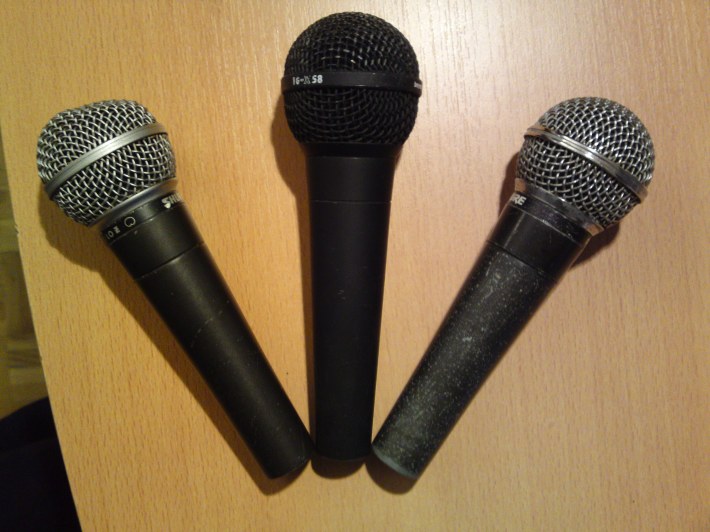
And here comes the big dynamic microphone shootout with a focus on vocal recording. The reason for me doing this comparison was the need for a good dynamic microphone for recording vocals in a live situation/ recording. As microphone bleed might be a problem in some cases, my aim was to figure out which dynamic microphone would be suited best for my demands. I also added two large diaphragm condenser mics to the shootout in order to find out, how dynamic microphones would compare to those.

There are 2 singers in the game, one female and one male singer, whereas the male singer was recorded with only the most common dynamic microphones.

This shootout is by far nothing scientific, as there certainly was a difference in the singers’ performance. This shootout is only meant to show the overall character of the microphones. Furthermore I decided not to use a high-end preamp but a standard interface preamp, so this situation would also apply to people on a low budget. It’s the SPL preamps in the Terratec Phase X24 FW. I’m convinced that a more expensive/ better preamp would bring out more details and depth in the recording.

All mics except the condenser ones were used without pop shield. We tried to always keep the same distance to the mics due to the proximity effect, which used to be about 2 cm.

Last but not least the biggest issue for me was to find a way to match levels between the different recordings. As percieved loudness is a decisive force in the psychoacoustical perception of sound, (meaning that you will like better what is louder) even a 0.5dB difference can influence the decision made by the listener. Therefore I tried to match the average RMS Level of each individual recording. In my opinion this works much better than just normalizing the individual tracks to the same level.

Here we go again, the candidates are (from left to right):

  • Shure Sm58
  • Shure Sm58 Transformerless MOD
  • Shure Sm57
  • Beyerdynamic M400 / Soundstar MkII (“A poor man’s Sm7”)
  • Shure Sm7b
  • ElectroVoice RE20
  • Heil PR30
  • Sennheiser MD441
  • Sennheiser MD421

Condenser Mics are:

  • Audio Technica AT4040
  • Microtech Gefell UM70

Special thanks go to GhostCity Recordings / Jan Kerscher for letting me use all the great mics  and to Mia Hilgart / Jan Kerscher for their performance! (and for making my day 🙂 )

Image

Soundfiles:

Here is a direct link to the .zip archive with the files in 320 kbs:

http://www.fileden.com/files/2009/7/21/2516851/Dynamic%20Mic%20Shootout/DynamicMicrophoneShootout.zip

More interesting stuff is about to come, so STAY TUNED and SHARE if you like !!!

Image

Microphone Shootout ShureSm58 vs Shure Sm58 MOD vs Beyerdynamic TG-X58

Image

Hier eine kleine Ergänzung zum vorhergehenden Post:

Die Soundfiles bieten einen Vergleich zwischen dem modifizierten Sm58, dem original Sm58 & einem Beyerdynamic TG-X 58!

Der Unterschied ist zwar nicht groß, auf ordentlichen Lautsprechern lässt er sich jedoch v.a. bei den Sprachaufnahmen deutlich heraushören!

Die Gitarrentracks wurden alle gereampt, um eine möglichst gleiche Aufnahmesituation zu gewährleisten!

Dies ist natürlich kein wissenschaftlicher Vergleich, d.h. ich kann leider nicht mit Messdiagrammen dienen, allerdings habe ich versucht die selbe Aufnahmesituation (Mikrofonabstand, etc.) bei allen Aufnahmen zu gewährleisten!!!

Viel Spaß damit!

VOX:

Guitar:

Clean:

und Crunch:

Shure Sm57/58 transformerless Mod

Das heutige DIY Projekt:

Shure Sm57/58 transformerless Mod 

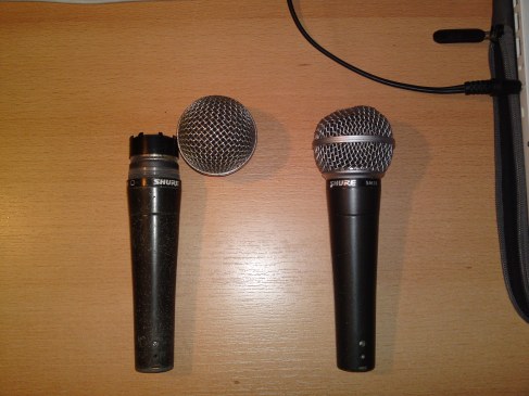
Wer kennt das gute alte Sm57/58 nicht!? An sich ein wirklich gutes dynamisches Mikro, welches aber auch so seine Tücken hat. Was mich immer furchtbar gestört hat, waren v.a. die dominanten Tiefmitten. Es gibt allerdings einen einfachen Trick, mit welchem man dem Mikro ein wenig auf die Sprünge helfen kann! Man muss hierbei lediglich den Übertrager aus dem Mikrofon entfernen.

Diese Modifikation rentiert sich v.a. für alle, die sowieso über mehrere Sm57/58er verfügen und gerne eine Alternative hätten. Da diese Modifikation allerdings auch ein paar Nachteile mit sich bringt, ist sie eher für den Einsatz des Mikros im Studio/Recordingbereich gedacht!


Die Vor- & Nachteile der Modifikation auf einen Blick:

+ Klang (offener, weniger Tiefmitten)

+ “Impulstreue”

– 10dB weniger Output

– verschlechterte SNR

– Ausgangsimpedanz entspricht nicht mehr den üblichen Spezifikationen (PreampEingangsImpedanz kann eine größere Rolle spielen -> Impedanzanpassung)

ACHTUNG: Durch die Modifikation erlischt jeglicher Garantieanspruch!


Das TapeOp Transformerless Mod funktioniert kinderleicht, man braucht lediglich ein wenig Geschick im Umgang mit dem Lötkolben!

Also here we go:

Was wir benötigen:

– Lötkolben, Lötzinn, (Lötpumpe);

– 3 isolierte Kabel (f. Hot,Cold & Shield)

– einen alten Eimer, Wasserkocher

– kleine Schraubenzieher, spitze Zange, sonstiges Werkzeug

Image

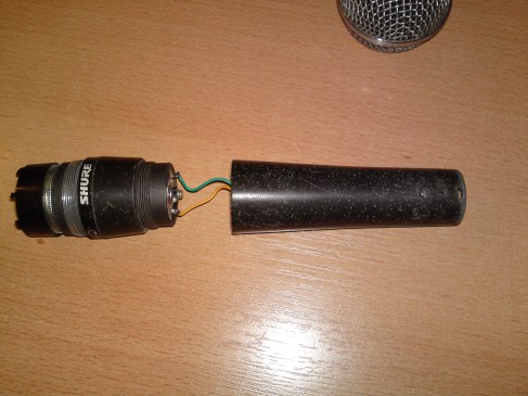
  • Mikrofonkorb und anschliessend “Mikrofonkapsel” abschrauben

Image

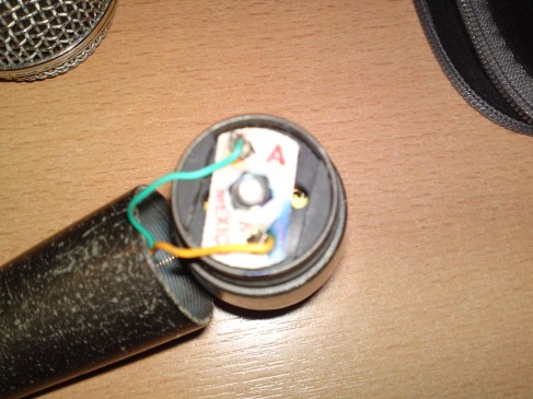
  • Notieren der Farbe der an der Kapsel anliegenden Kabel (da dies später für die Polarität wichtig wird!!!)

Image

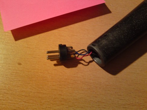
  • XLR Stecker ausbauen, dazu Schraube am unteren Ende hineindrehen 
  • Farben der Kabel an den verschiedenen Pins notieren (in meinem Fall war das: Masse=Schwarz, Hot=Blau, Cold=Rot)

Image

Image

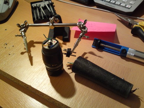
  • Kabel von Kapsel & XLR Connector ablöten

Image

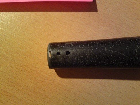
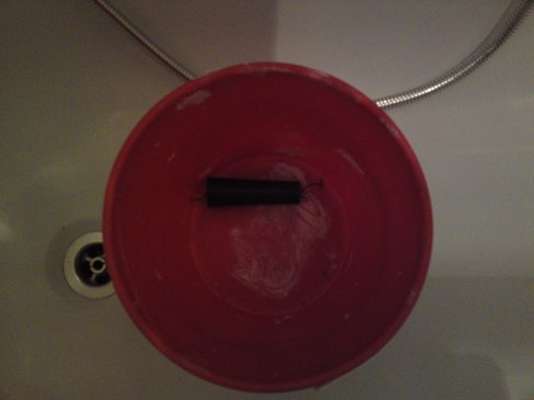
  • NUR(!!!!) das hintere Teil des Mikros (NICHT die Kapsel –> Membran freut sich nicht über Wasser) in einen alten Eimer geben und mit kochendem Wasser übergießen und c.a. 3 Minuten “ziehen” lassen 🙂
  • Der Sinn an der Geschichte ist, dass sich der Industriekleber, mit dem der Übertrager im Mikrogehäuse befestigt ist, schmilzt und man diesen herausnehmen kann!
  • TIPP: Ich hab in andere Foren auch von Leuten gelesen, die das Mikrogehäuse vorher in einen luftdichten Gefrierbeutel gepackt haben, damit nichts nass wird, denn ACHTUNG!!!!!!!!!!!! –> Durch das Wasser wird natürlich der eingebaute Übertrager unbrauchbar und ein Wiedereinbau unmöglich. (Mir sowieso egal!)
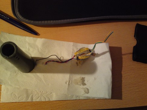
  • Nach c.a. 3 Minuten nehmen wir das Gehäuse aus dem Wasser (VORSICHT HEIß! – Am besten mit einem Topflappen anfassen) und ziehen den Übertrager & das obenliegende Kupferblättchen an den hervorstehenden Kabeln nach oben aus dem Mikrofongehäuse & lassen alles trocknen

Image

Image

Image

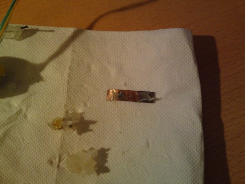
  • Bei alten Sm58ern wird das Kupferblättchen für die Verbindung mit der Gehäusemasse benötigt. Sollte dieses Blättchen bei euch vorhanden sein, werden wir es nun zuerst reinigen und unser NEUES Massekabel an einer sauberen Stelle anlöten!
  • JETZT wird es ein wenig frickelig: Man muss das Blättchen irgendwie mit dem Gehäuse verlöten, man kann es ruhig auch halbieren, um Platz zu sparen. Ich habe es direkt an die Seite gelötet & es funktioniert einwandfrei!
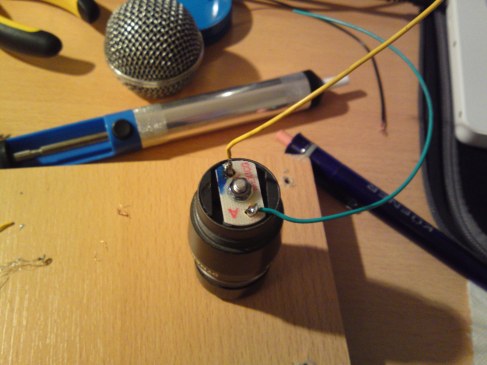
  • Neue Kabel an Kapsel löten (Länge beachten & Farbcodierung)

Image

  • Kabel durch das Loch nach unten führen & Kapsel anschrauben

Image

  • XLR Connector anlöten, folgende Pinbelegung:
  • PIN 1 : Masse/Shield –> Schwarz
  • PIN 2 : hot/Signal + –> das, was vorher türkis war
  • PIN 3 : cold/Signal – –> das, was vorher gelb war
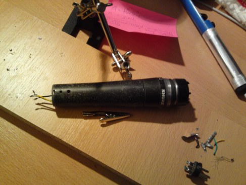
  • Jetzt nur noch rin mit dem XLR Connector und festschrauben !!!
  •  Ferdsch!!!!!!


Hier noch ein Link zu einem Youtube Video in dem alles nochmal anschaulich erklärt wird: