Building a passive volume control / input-output switch

What’s the convenience of having an analog volume control over the built-in volume control in most interfaces? Most important is the fact, that by turning down the volume with the built-in volume control, the bit depth will drastically decrease, as most interfaces will reduce volume in the digital domain. (Except some high end gear like the UA Apollo!) So why spending hundreds of dollars on high end gear, when one won’t be able to hear, what’s really going on, even if your signal chain only contains the best gear (Monitors, converters, etc.). As a rule of thumb, 6db equals 1 Bit Resolution, meaning that reducing the output of your interface by e.g. 24 db will result in a resolution of only 20 Bits. On the other hand it’s quite handy having a monitoring station, where it’s possible to switch between different monitor pairs or different input sources.
The reason for me building a passive volume control myself, though there are alternatives galore on the market, was simply because I wanted to build something that would a) last for long and b) consist of high quality parts. There’s obviously nothing wrong with the current products one could buy, but for a price of 50 Euros average, one should not expect extraordinary quality. The DIY volume control is also about 50 Euro, but contains much better parts.
Now the question arises, why passive? Well, one the one hand it’s absolutely linear up to 50kHz (as long as cable length does not exceed 10 meters → HiCut / RC-circuit), on the other hand it’s just simple to build and straightforward. It’s only necessary to have a little soldering experience.
The most important part in this circuitry is the pot, this is why I chose to use an ALPS pot, that definitely provides a better gang-error (Gleichlauf) compared to the pots used in the common cheap volume controls. This is btw the reason to most high-end manufacturers for choosing an active circuitry due to the ability of providing equal volume on both channels (L&R).
There is only one problem, that still has to be considered: If I wanted to build a balanced volume control, I would need a four-gang pot, which is pretty big and expensive, because every signal theoretically needs it’s own “layer” on the pot. (2 Signals Hot/Cold for each L&R.) Therefore I found a solution on the web:
I used the pot in parallel as shunt, with the so-called shunt mod, so a dual-gang pot was just fine. The only drawback is that you have to connect all grounds together, so the whole gear should use the same power outlet, as well as all the cables’ shields should be connected.
The necessary switches should be four-pole three-position rotary switch (4×3), the middle position will form the “mute position” with nothing connected to it’s poles.
(It’s btw also possible to connect all of the poles on the output, thus being able to connect 3 monitor pairs!!!)
In the BOM you will also find 4 x 4K7 Ohm resistors, which will attenuate the signal by approximately 6dB, so the control range on our controller will be more “precise”.
BOM (Bill of materials) / What we need:
(I ordered those at BanzaiMusic Berlin)
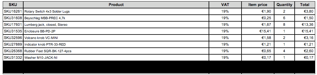
Attention: The enclosure I used turned out to be too small for all the parts, so I ended up with a 2 In 4 Out switch/control, so a bigger enclosure is necessary for a 4 In 4/6 Out switch!!!
and
ALPS dual-gang 10K logarithmic pot


HOW TO:
The entire procedure might not be complicated regarding the circuitry, but it’s quite an effort soldering all the necessary connections, therefore I will show step-by-step how to create your own DIY volume control.
1. Unpacking / Preparing
There are a few things to consider before we start soldering. After drilling the holes for the pot and the 2 switches in the enclosure, we need to clip off the switches’ “noses” to the needed length. This might sound quite trivial, but for beginners this definitely will be a problem. In the first place I also asked myself, how I can make all the parts fit my enclosure. There’s also a “nose/pin” on the pot, which should be removed by clipping off. (It’s also possible to drill a hole for the pin, but that’s much more complicated imho!)
2. Connecting the pot
At first I would recommend soldering all connections to the pot. Therefore the pot will not be connected in a normal way, but as “shunt” pot. Thus the pin layout on the pot is the following for each “layer” (L = Layer/Gang1; R = Layer/Gang 2):
1 In & Out Hot (Signal → R = 4K7Ω → Pot → Signal)
2 & 3 Connected together – In & Out Cold (Signal → R = 4K7Ω → Pot → Signal)
(Original pin layout would be: 1 Ground; 2 Out; 3 In)
For help check out the following pictures!!!

Regarding the upper picture: We will not connect pin 2&3 to ground, but instead this will be the cold signal !!!
3. Connecting the rotary switches
In the middle of each switch there are 4 pins for the respective signals:
A Left In / Out Hot
B Left In / Out Cold
C Right In / Out Hot
D Right In / Out Cold


The other pins, which are organized as circle will determine which signal will go to the pins in the middle and vice versa. Each pin in the middle will belong to 3 pins in the circle. In the next step the cables coming from the pot have to be soldered to the middle pins of the input switch, as well as to the ones on the output switch. Finally the “circle” pins have to be soldered to the contacts on the input / output stereo jacks. This example will make clear which cables the solder lugs have to be soldered to:
For the input switch:
Pin 1 = Signal 1 Left In Hot →
Pin 2 = None → Pin A = Left Out Hot
Pin 3 = Signal 2 Left In Hot →
Pin 4 = Signal 1 Left In Cold →
Pin 5 = None → Pin B = Left Out Cold
Pin 6 = Signal 2 Left In Cold →
Pin 7-9 contains Signal 1 / 2 Right In Hot, Pin 10-12 Right In Cold
For the output switch:
→ Pin 1 = Out 1 Left Hot (Speaker pair 1)
Pin A = Left Out Hot → Pin 2 = None
→ Pin 3 = Out 2 Left Hot (Speaker pair 2)
→ Pin 4 = Out 1 Left Cold (Speaker pair 1)
Pin B = Left Out Cold → Pin 5 = None
→ Pin 6 = Out 2 Left Cold (Speaker pair 2)
etc…
Now there’s still one thing missing. All the stereo jacks’ grounds have to be connected together from the input side to the output side!
After all the soldering insanity and assembling all the parts this thing should somehow look like this (as I already mentioned I left out the 2nd input due to missing space):


The switches now have the follwing function:
→ Position A: Input A
Input switch → Position B: MUTE
→ Position C: Input B
→ Position A: Speaker pair 1
Output switch → Position B: None / MUTE or additional speaker pair
→ Position C: Speaker pair 2
The volume control / switch just works fine and really solved a lot of problems for me. I absolutely recommend reading the instructions posted in the following files / links, which were quite a big help to me:
http://www.world-designs.co.uk/forum/showthread.php?t=5795
If there is something I got wrong regarding electronics, please feel free to comment or improve something regarding the circuitry!!! Feel free to ask, if there’s something that did not become clear!

Hi Hannes.
Nice project but i have want to mention the noise you get from these potentiometers as the middlecontact is rubbing on carbonfield (can explain it better in german ;). so this is a “cheap” way and maybe ok for a very “hot” signal. usually these pots are used in a VCA environment (not in the audio-path), if you want to build a high end attenuator, this would be a better way:
http://diyaudioprojects.com/Misc/DIY-Stepped-Attenuator/
Don`t want to start hating your project, just want to mention the other way 😉
Greetings and respect, Uwe
Thanks for the reply! Hm, the pot works just perfectly, as far as I know those are also used for this specific application. So far I haven’t realized any noise, but I also know those pots can be sensitive towards humidity and temperature differences, meaning that in this case they might produce “scratching noise”! Greetings, Hannes!
Thanks for the link btw! 😉
Hello Hannes,
I am currently attempting to recreate your project here. Im wondering about two things: First, how do I use the stereo jack as just a single, stereo (TRS) channel for headphones? How would that look as one of the outputs on the rotary switch? Second: I would like to have a mono out for my sub, so how do I wire that in as a parallel output with the other two main outputs?
L R
^ ^ > (mono sub out)
^ ^ ^
This is my current idea: input L—— [ MONO/STEREO switch]—— [VOLUME] —- [OUTPUT switch] > > L
input R—— [ ] —— [ ] —- [ ] > > R
\/
Headphone (TRS)
The formatting was all messed up above. Hopefully this one works
……………………………………………………………………………….L R
………………………………………………………………………………..^ ^……> (mono sub out)
………………………………………………………………………………..^ ^ ^
input L—— [MONO/STEREO switch]——[POT]—-[OUTPUT switch] > > L
input R—— [MONO/STEREO switch]——[POT]—-[OUTPUT switch] > > R
…………………………………………………………………………………\/
……………………………………………………………………….Headphone (TRS)
********* Correction************
After some reading, I will have the stereo/mono switch AFTER THE POT and BEFORE THE OUTPUT switch.